
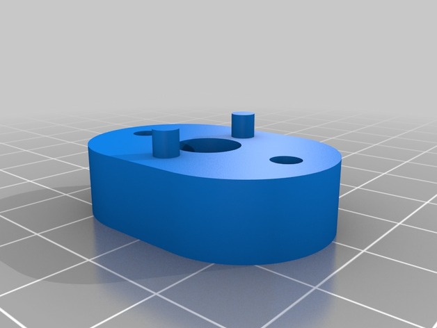
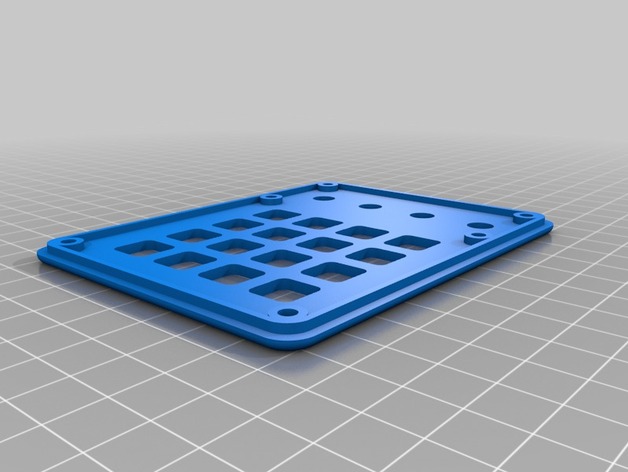
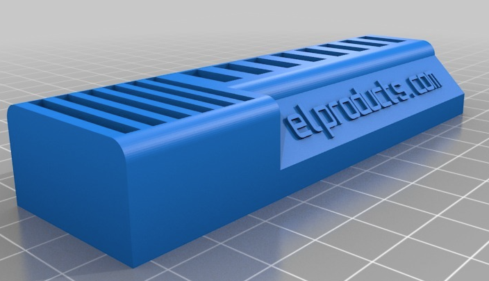
I just posted another 3D Printer Project on my YouTube Channel. This time I created a box that holds a breadboard with space underneath for storing components. The box is shaped like an 8-pin Microcontroller. I used a thingiverse design from user tetralite who created an actual size 8-pin microcontroller 3D print design. So I took the design and made it much larger to fit a breadboard on top.
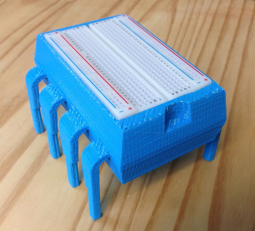 | 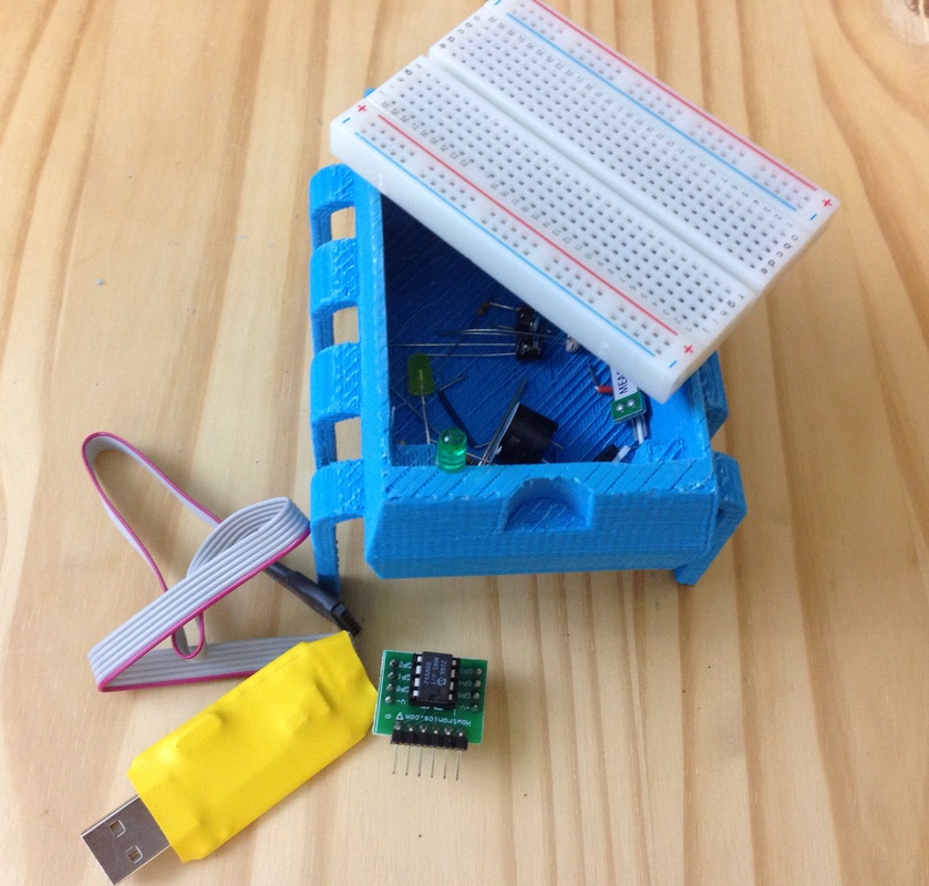 |
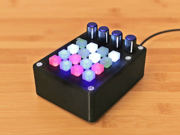
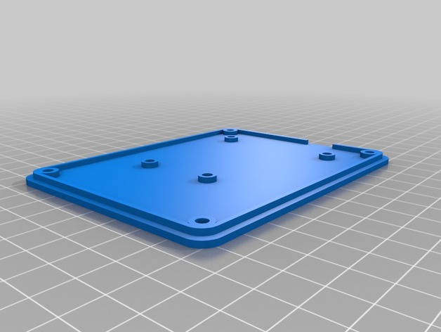
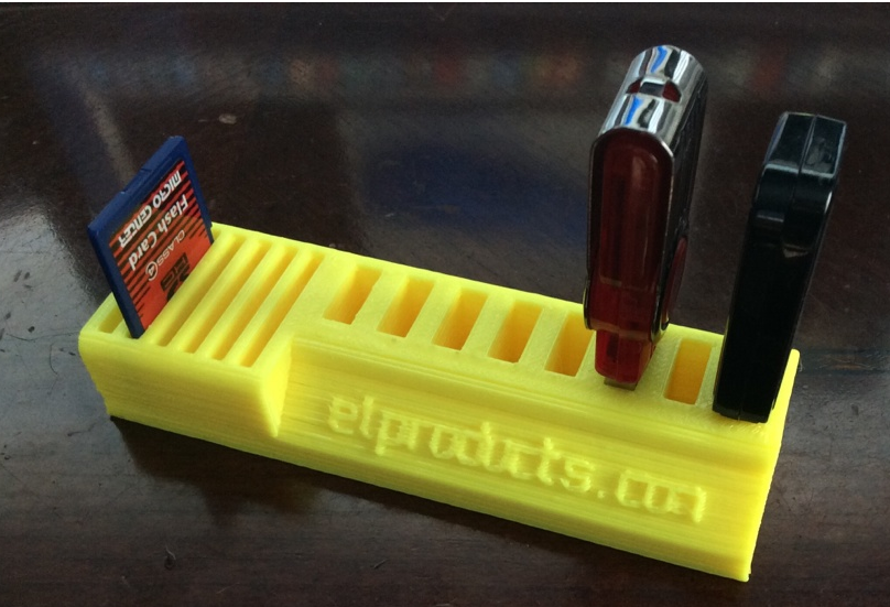
The breadboard is held up by four posts underneath but also has lots of empty space inside the microchip body. This allows you to store components inside. In fact it fits all the components I used in my book "Programming PICs in BASIC" which uses an 8-pin Microcontroller.
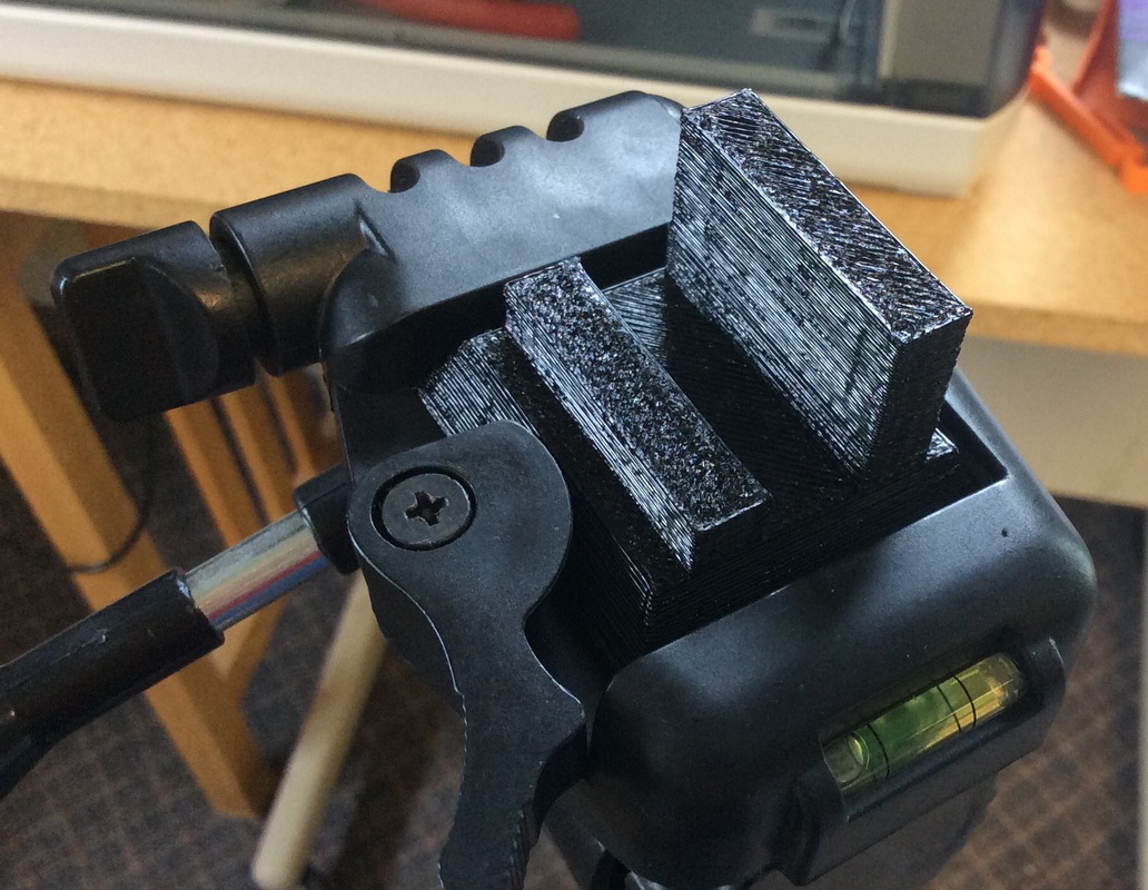
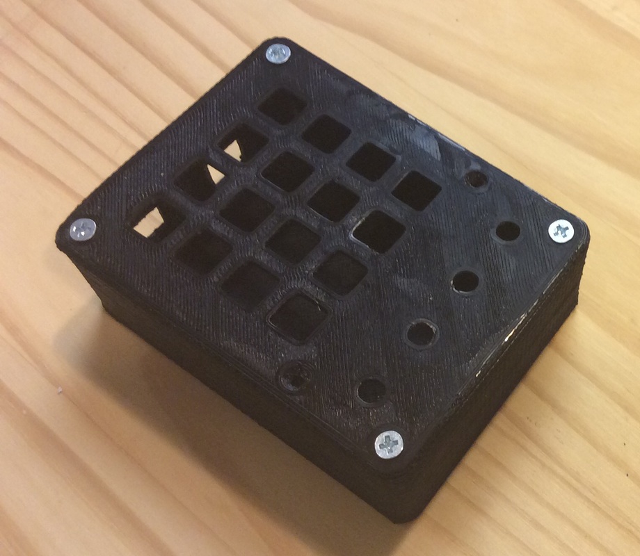
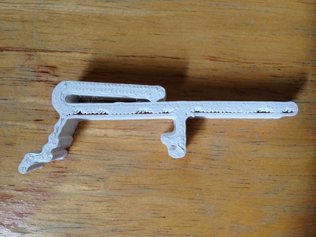
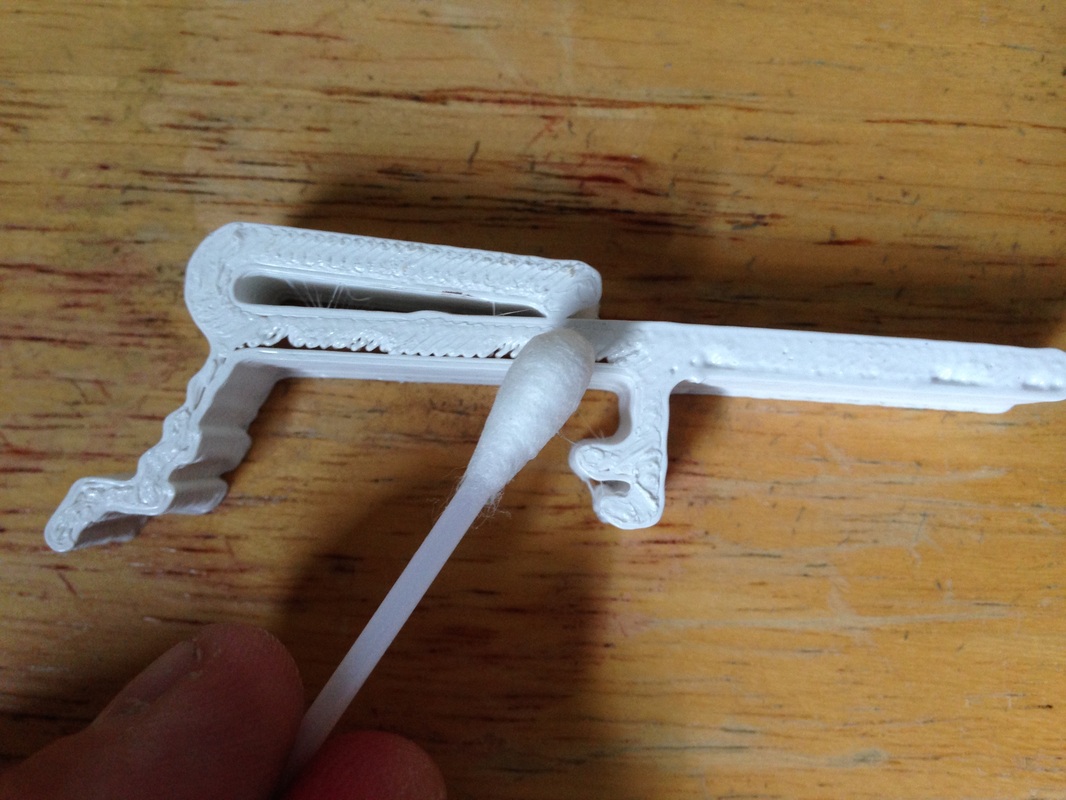
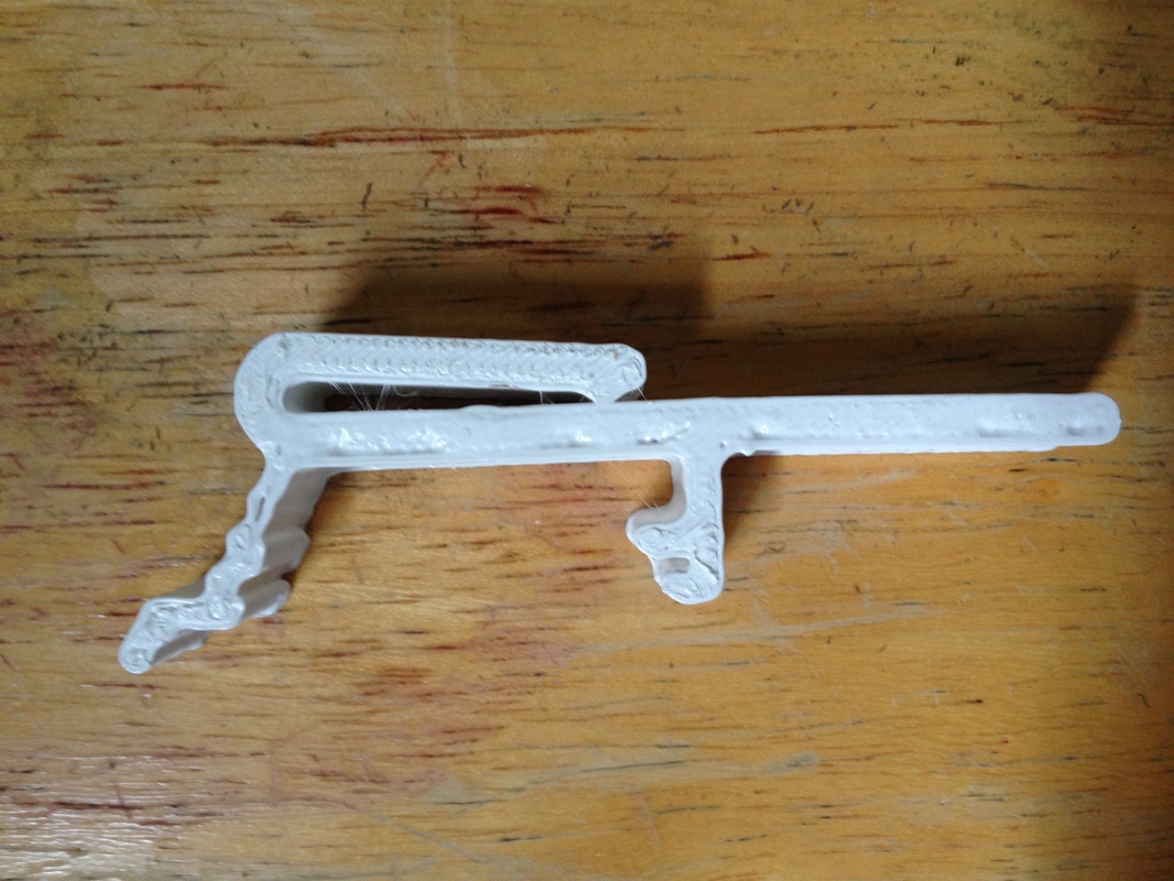
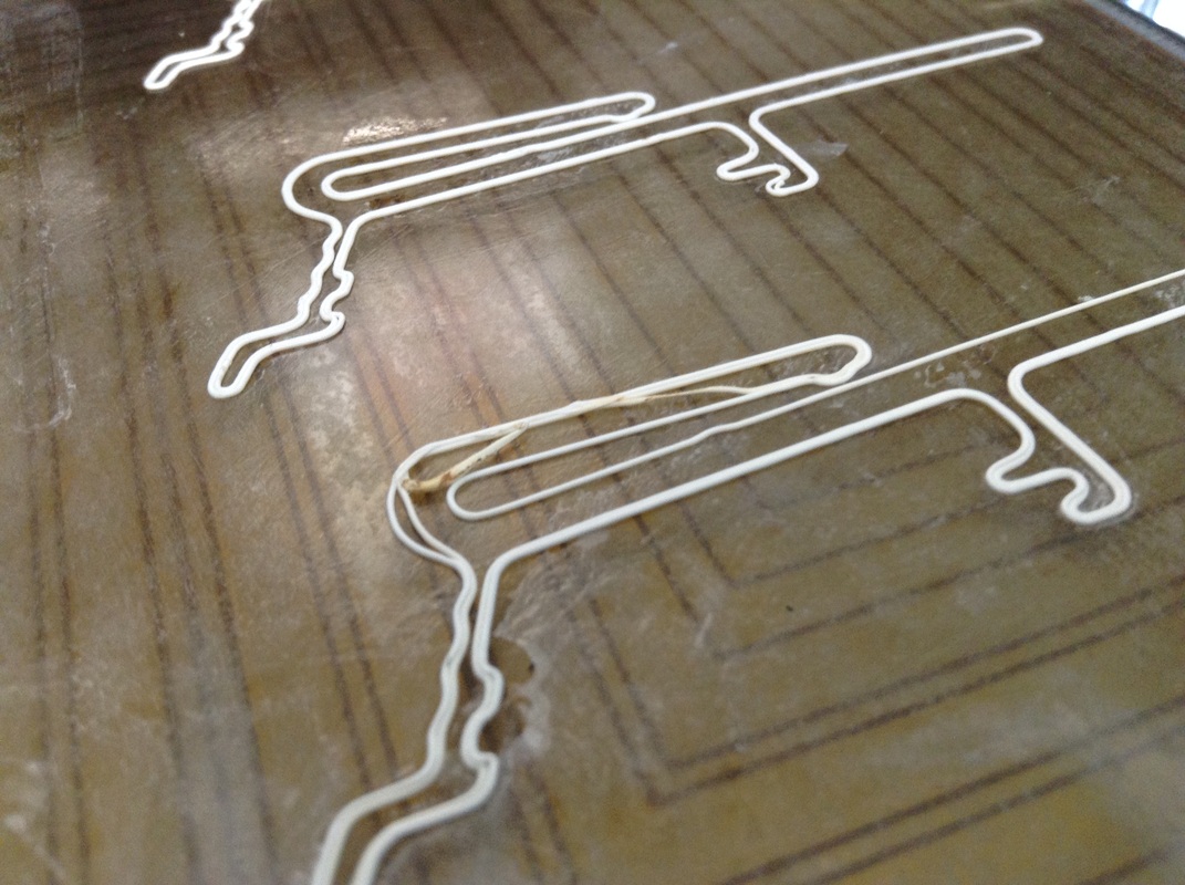
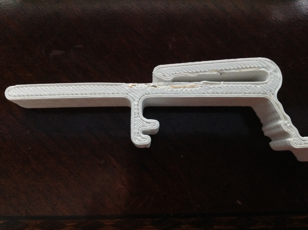
I used TinkerCad for the modifications and then printed the design on my Davinci 1.0 printer. The design had a lot of support material to be removed but it came out very solid and smooth with a little clean-up. I also used a raft as the base to try and prevent any warpage which seemed to work well. You can see the full project description in the video below.
I used TinkerCad for the modifications and then printed the design on my Davinci 1.0 printer. The design had a lot of support material to be removed but it came out very solid and smooth with a little clean-up. I also used a raft as the base to try and prevent any warpage which seemed to work well. You can see the full project description in the video below.
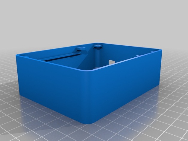
This started out as just a fun project that grew bigger as I thought about it. At first I only recessed the breadboard into the top of the chip but then realized all that plastic under it could be hollowed out for storage. I released the .stl file on Thingiverse for anybody to build. Check it out and let me know if you build one too.


 RSS Feed
