Understanding A Microchip PIC Hex File
When you create a software program for a Microchip PIC, the compiler will produce an assembly file that gets assembled into a binary file, with a .hex suffix, to be loaded into the microcontroller. The binary file contains the 1’s and 0’s that make up the machine language commands that ultimately control the inner workings of the microcontroller. There are times when you may need to know the structure of that binary file especially if you want to build a custom bootloader program for programming the microcontroller. In this article I’ll describe how to understand the structure of that binary file.
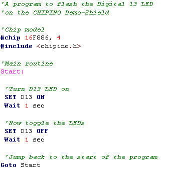
First let’s create a simple program in Great Cow Basic. This program will flash the LED connected to pin Digital 13 on a CHIPINO module.
First let’s create a simple program in Great Cow Basic. This program will flash the LED connected to pin Digital 13 on a CHIPINO module.
The assembly code file produced is available and can be easily viewed in a window next to the Basic file. I’ll use this for reference in sections below. But first lets look at the .hex file produced when this assembly file gets assembled into the .hex binary file.
;Vectors
ORG 0
goto BASPROGRAMSTART
ORG 4
retfie
;**************************************************
;Start of program memory page 0
ORG 5
BASPROGRAMSTART
;Call initialisation routines
call INITSYS
;Automatic pin direction setting
banksel TRISB
bcf TRISB,5
;Start of the main program
;A program to flash two LEDs on PORTB, bits 0 and 1
;Chip model
;Main routine
START
;SET D13 ON
banksel PORTB
bsf PORTB,5
;wait 1 sec
movlw 1
movwf SysWaitTempS
call Delay_S
;SET D13 OFF
bcf PORTB,5
;wait 1 sec
movlw 1
movwf SysWaitTempS
call Delay_S
;goto Start
goto START
BASPROGRAMEND
sleep
goto BASPROGRAMEND
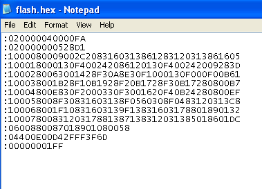
The program is compiled and assembled and produces a binary .hex file as seen the Figure 2. This file was opened in a notepad text editor so this is the raw file. It would seem very difficult to understand the code from that strange set of characters but let’s break it down and you’ll see it's not that confusing.
First off, understand that this .hex file is in Intel Hex32 format. This means it can support 32 bit wide address memory devices. But the format is broken up into an upper 16 bits and a lower 16 bits. The upper 16 bits are known as the extended address.
Every new line begins with a colon. Then the numbers and letters that follow are hexadecimal codes that are control characters, address locations or data bytes. Each line in the file has this format:
:BBaaAATTDDCC
BB contains the number of data bytes on line.
aaAA is address in memory where the bytes will be stored. This number is actually doubled which I’ll cover in a bit. Also the lower byte is first aa followed by the upper byte AA.
TT is the data type.
00 - means program data.
01 - means End of File (EOF).
04 -means extended address. It indicates the data value is the upper 16 bits of the address.
DD is actual data bytes which contain the machine code that your program created. There can be numerous bytes in one line. The BB value indicates how many bytes are included in the line.
CC is calculated checksum value for error monitoring. It’s a 2s-complement calculation of: BB + AAAA + TT + DD.
So let’s look at the first line.
:020000040000FA
02 indicates the number of bytes on the line. In this case there are two bytes.
0000 is the memory address to place the bytes but its value was multiplied by 2. So normally we would divide the address by 2 but in this case 0000 / 2 = 0000. So the address is 0000.
04 means this is the extended address. So the data contains the upper 16 bits of the address. Any lower bit addresses that follow this line will use these upper bits until a new 04 line changes the upper bits.
0000 this is the upper 16 bits of the address indicated by the 04 data type.
FA is the 2’s compliment of the sum of the bytes: 02 + 00 + 00 + 04 + 00 + 00.
Note: 2’s compliment is just the binary value, inverted and then 1 added. Then the result converted to .hex format.
i.e.
02 + 00+ 00 + 04 + 00 + 00 = 06 = 00000110 binary
00000110 inverted = 11111001
11111001 + 1 = 11111010 = FA hexadecimal
So this first line just says the upper address for all future bytes will have an upper (extended) address of 0000 and it will start at memory address 00000000 in the Microchip PIC.
The next line breaks down this way:
:020000000528D1
02 indicates two data bytes.
0000 is the address again.
00 is the data type so the data bytes are program data.
0528 are the two data bytes. But these are reversed since the lower byte is first so this is really 2805 hex.
D1 is the 2’s compliment checksum.
So at address 00000000 (extended and lower word combined) the program data byte 2805 is stored. But what does that byte mean?
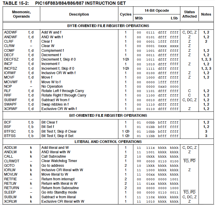
For this we have to consult the PIC16F886 data sheet (Figure 3). In the data sheet is the Assembly code instruction set. And for each instruction, the table 15-2 below, shows a 14 bit opcode. This is the binary machine code for the instruction.
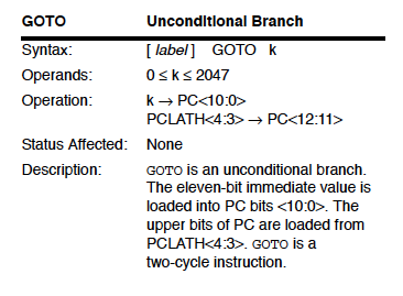
So converting 2805 to binary we get 0010100000000101. Since the PIC16F886 uses a 14 bit opcode we can ignore the first two bits which are zeros. This leaves us with 10100000000101. If we then scan the opcode list we will find that code matches the GOTO instruction 10 1kkk kkkk kkkk. The kkk.. portion represents the address to goto. In this case the value after the 101 for goto leaves a value of 00000000101 or hex value 05.
So this would indicate that this line in the .hex file represents a GOTO 0x05 command line.
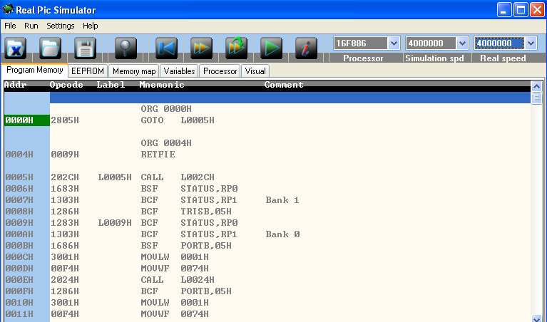
Let’s see if our analysis is correct. I’ll use the Real Pic Simulator to load the .hex file in as it has the ability of disassembling the .hex file back into the assembly commands. Figure 4 shows the results and the first line confirms our analysis.
But what is L0005H?
This is actually a label created in the dissassembler to represent where to “goto”. We have to look at the line at 0005h to see that label.
This is actually a label created in the dissassembler to represent where to “goto”. We have to look at the line at 0005h to see that label.
And this confirms our analysis was correct. The GOTO 0005h took the program to address location 0005h.
We can also see it in the upper section of the assembly file from earlier.
The assembly directive ORG 0 indicates that the code below it should be placed at memory address 0000h. At that line is a command line:
GOTO BASPROGRAMSTART. Look a little farther down and we see an ORG 5 for address 0005h and there is the label BASPROGRAMSTART.
So our GOTO 0005h matches the assembly file as well.
ORG 0
goto BASPROGRAMSTART
ORG 4
retfie
;**************************************************
;Start of program memory page 0
ORG 5
BASPROGRAMSTART
So now we can move on to the next line.
:1000080009002C2083160313861283120313861605
It looks like a lot is going on there. Lets break it down.
10 indicates 16 data bytes. Remember this is a hexadecimal value so 10 hex is actually 16 decimal.
0008 is the address and this time we have to divide it by 2. 0008 / 2 = 0004h.
So the data will be placed at 00000004h memory location.
00 is the data type so the data bytes are program data.
0900 is the first two data bytes. But again these are reversed since the lower byte is first so this is really 0090 hex.
This byte is followed by 14 more so I’ll list them in high byte –low byte format:
202C
1683
1303
1286
1283
1303
1686
05 is the 2’s compliment checksum.
Now I won’t go through them all but we can look at the first couple and convert them to the 14 bit opcode by eliminating the first two zeros.
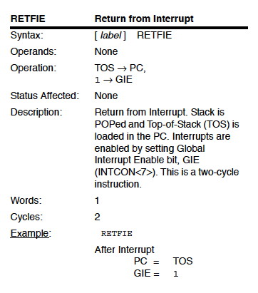
0009 or 00000000001001 is the exact match for the RETFIE command or RETurn From Interrupt Enable.
RETFIE – 00000000001001
So at memory location 0x0004 is RETFIE
202C or 10000000101100. This has to be broken down.
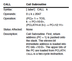
100 – matches the CALL Subroutine command.
CALL – 100kkkkkkkkkkk
The K’s represent the memory location to call or jump to.
00000101100 – is the memory location to call which is 2C hex or memory location 0x002C
So at memory location 0x0005 is CALL 0x002C
100 – matches the CALL Subroutine command.
CALL – 100kkkkkkkkkkk
The K’s represent the memory location to call or jump to.
00000101100 – is the memory location to call which is 2C hex or memory location 0x002C
So at memory location 0x0005 is CALL 0x002C
1683 or 01011010000011. This has to be broken down.
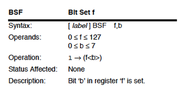
0101 – matches BSF command or Bit Set File register
BSF - 0101bbbfffffff
The BSF has two parts; bbb and fffff.
bbb is the bit location to set.
fffff is the address for the Register that contains the bit.
fffff – is 0000011 or memory location 0x0003h.
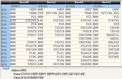
If we look at the memory map of the PIC16F886 (in the Real Pic Simulator) we see that the STATUS register is at the 0x0003h memory location.
bbb – is 101 or bit number 5.
So bit 5 of the Status register will be set to a 1 when this instruction is executed. This is the RP0 bit if you were to look at that register in the data sheet.
So at memory location 0x0006 is BSF RP0, STATUS
So bit 5 of the Status register will be set to a 1 when this instruction is executed. This is the RP0 bit if you were to look at that register in the data sheet.
So at memory location 0x0006 is BSF RP0, STATUS
If we go back and look at Figure 4 again, we see the code matches our analysis.
I could go on through the rest of the file but I think I’ve shown you how it all works.
The last line in the .hex file is:
:00000001FF
This line breaks down this way:
00 indicates no data bytes.
0000 is the address again but this is meaningless since we don’t have any data bytes to store.
01 is the data type which indicates this is the end of the file.
FF is the 2’s compliment checksum.
This line indicates you have reached the end of the file.
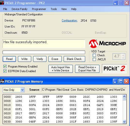
As a final step, lets load the .hex file into the PICkit 2 programmer window to see what it shows. The program memory window shows the Address on the very left and the data words in hexadecimal across the screen.
i.e.
0000 2805 3FFF 3FFF 3FFF 0009 202C 1683 1303
You can see that the hex values we pulled from the .hex file are showing up as we expected in the memory view. 2805 is the GOTO 0x0005 command. Unused memory locations are set to 3FFF or all ones. So the locations between the GOTO 0x0005 and the 0009 RETFIE command at location 0x0004h are filled in with the 3FFF. The RETFIE 0009 is followed by the 202C CALL 0x002C followed by the 1683 BSF Status, RP0 command.
Conclusion
So hopefully you have learned enough about the structure of this Microchip PIC .hex file format to be able to decode any .hex file you need to. With all the disassembly tools, its easily handled for you but now you can easily understand your programs down to the 1’s and 0’s level.
Conclusion
So hopefully you have learned enough about the structure of this Microchip PIC .hex file format to be able to decode any .hex file you need to. With all the disassembly tools, its easily handled for you but now you can easily understand your programs down to the 1’s and 0’s level.

