Electronic Products
Find us here:
  • Chuck's Blog
    • Blog Posts Archive
    • Disclaimer
  • YouTube Channel
  • About Chuck
    • About Chuck
    • Stock Car Racing
  • Books
    • Embedded C Books >
      • cbookfiles
      • cbook2files
      • cbook3files
    • BASIC Books >
      • Programming PICs in BASIC_vol1
      • PICBasic Book Support
      • Basic Atom Book Support
    • Other Books >
      • Arduino Book
      • chipkitbookfiles
  • 3D Printing
    • Fabrikator Mini
  • Getting Started with PICs
    • BASIC Programming
    • C Programming >
      • C Compilers
  • Build Your Own PICKit 2
    • PICkit 2 Starter Kit
  • CHIPINO
    • Shields
  • CHIPAXE Breadboard Modules
  • Understanding Hex Files
  • chipKIT
  • Newsletter Archive
  • Contact
  • Retired Designs
    • BasicBoard
    • Ultimate OEM
    • Maximite BasicBox
    • Maximino
  • Downloads
  • Kickstarter Projects
    • Demo-Shield
  • Great Cow Basic Site
  • Buy Hardware
  • Links I Recommend

Real Pic Simulator

6/28/2013

5 Comments

 
I was searching for a graphical tool to work with Snap Circuits when I found the Real Pic Simulator. This simulator is awesome in my opinion. It cost $29 for the full non-commercial version and to me, it was worth it. 

The simulator works with the .hex file created by the compiler of your choice and then allows you to run it on simulated electronic components. There are LEDs, switches, potentiometers, LCDs and more. Amazingly it also includes a graphic LCD based on the KS0108 chip. I created a Great Cow Basic project for that recently and had a hard time getting everything working correctly but after several hours had it working. I loaded that same .hex file in Real Pic Simulator and tested it on the graphic LCD and it displayed perfectly. I wish I had this before.
Picture
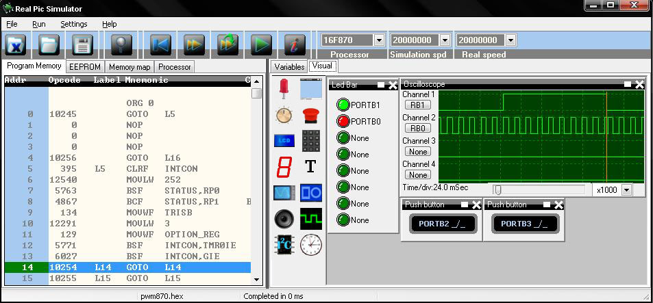
The .hex file is disassembled back into PIC assembly code so you can watch the code run during the simulation. You can set break points and then step through the assembly commands. You can split screen and have the assembly code on one side and the hardware simulation on the other. 

The GUI objects also includes an oscilloscope object which is more like a logic analyzer. There is also a function generator but I haven't tried that out yet so I'm not sure exactly how well that works.

Bottom line is, this tool works great with any PIC development package to give you a quick way to test typical circuitry blocks with code.

Check it out at:
http://digitalelectrosoft.com/pic-simulator
5 Comments

MakerCase Box for BasicBoard

6/19/2013

2 Comments

 
I just completed my first box with the MakerCase.com online tool for designing laser cut boxes. The software is easy to use and getting better all the time. I decided to create a clear acrylic box for my BasicBoard design that has been sitting around on my bench for a while now.
Picture
BasicBoard Box as seen in MakerCase
I made a 4.1" x 2.8" x 1.25" box with holes in the top and bottom that line up with holes in the board. Then I added rectangular holes in the sides so I could easily access the switches, expansion ports, programming header and on/off switch. 

The edges have interlocking fingers to make the design easier to build and make a stronger box. The idea was to glue the sides together then hold top and bottom together with standoffs that will also hold the BasicBoard inside.

When the design was done, I had MakerCase generate the .svg file. This file was then taken to my local engraver (The Village Engravers in Milford, Michigan) who has an Epilog Laser. He typically just engraves trophies and plaques to pay the bills but he likes to help creators by also cutting out designs. It only took about 10 minutes to get two boxes cut out and give me two sets of the pieces shown below.
Picture
A little dab of superglue on the middle tab of the short sides was all I needed to make the sides bond together. I used some jack screws to mount the BasicBoard and then put all the pieces together as seen below.
Picture
Picture
Jack Screw
Picture
Standoff
I didn't have the correct length standoffs to place on top of the jack screws that will hold the BasicBoard tightly in place and also create the mounting screws for the top so I ordered some from Jameco.com. I hope to have them in a few days.

I also wanted text engraved into the top and bottom and had that in the final design but somehow the file would not load at the engraver. Fortunately I also had the non-engraved text version on the flash drive that loaded just fine so that was laser cut.

My head is spinning with ideas of what I can produce with this design software. And I'm already thinking of ways to get around the rectangular box design. If I put a hole in the center of one of the discarded cutout pieces, they can be sized to become robot wheels. Or make a large square box with large circle cutouts and then the large circle cutouts become the levels of a round robot base. And all this without ever having to learn a CAD/graphics program like inkscape or corel. How great is that?
2 Comments

Great Cow Basic----or Great Cow Assembly

6/9/2013

0 Comments

 
Great Cow Basic could actually be called Great Cow Assembly. This is because the compiler produces pure assembly code. By that I mean after running the compiler on your Great Cow Basic code you end up with a .asm file of the same name as your Great Cow Basic file. That .asm file can be directly loaded, built and simulated or debugged right in Microchip's MPLAB.

'A program to flash LED on PIN 13/PORTB5
'Chip model
#chip 16F1829, 16
'Main routine
Start:
 'Turn one LED on, the other off
  SET LATB.5 ON
    wait 1 sec
 'Now toggle the LEDs
  SET LATB.5 OFF
    wait 1 sec
 'Jump back to the start of the program
goto Start


You don't have to tweak anything. The configuration, variables, every command is presented just like you wrote it in Assembly code to start with. The only difference is your Basic commands are now comments.

;Start of the main program
;A program to flash LED on PIN 13/PORTB5
;Chip model
;Main routine
START
; SET LATB.5 ON
   banksel LATB
   bsf LATB,5
;wait 1 sec
   movlw 1
   movwf SysWaitTempS
   banksel STATUS
   call Delay_S
; SET LATB.5 OFF
   banksel LATB
   bcf LATB,5
;wait 1 sec
   movlw 1
   movwf SysWaitTempS
   banksel STATUS
   call Delay_S
;goto Start
   goto START
   BASPROGRAMEND
   sleep
   goto BASPROGRAMEND


I've seen many compilers make assembly files; that's what they do. But I've never seen one produce something so crystal clear as Great Cow Basic. It's really easy to see the assembly code produced from these BASIC commands. 

And what a great way to teach assembly language. Make a simple Basic language program that flashes an LED and then you can see how to setup the port registers, manipulate the bits and even switch banks of memory if needed. It's all done for you in pure assembly language. No hidden macros or cryptic defines. 

It does have some setup routines like the main Initsys subroutine where the registers, that get most beginner's in trouble, are handled for you. It's brilliantly simple and can easily be modified if you are an experienced assembly programmer.I am so impressed with this open source compiler. I plan to do a lot more with it in the future.

INITSYS
;OSCCON = OSCCON OR b'01111000'
movlw 120
banksel OSCCON
iorwf OSCCON,F
;SET ADCON0.ADON OFF
bcf ADCON0,ADON
;SET ADFM OFF
bcf ADCON1,ADFM
;ANSELA = 0
banksel ANSELA
clrf ANSELA
;ANSELB = 0
clrf ANSELB
;C2ON = 0
banksel CM2CON0
bcf CM2CON0,C2ON
;C1ON = 0
bcf CM1CON0,C1ON
;PORTA = 0
banksel PORTA
clrf PORTA
;PORTB = 0
clrf PORTB
;PORTC = 0
clrf PORTC

return

0 Comments

    Sponsors


    Picture
    Picture
    Picture

    Advertise here for only $25 per month. 170x50 pixel add with graphics (similar to Howtronics above). 
    Contact us at our contact form for more detail.

    Categories

    All
    3D Printer
    Chipaxe
    Chipino
    Chipkit
    CNC
    Copper Connection
    Dot Matrix
    Elproductsnews
    Expresspcb
    Graphic Lcd
    Great Cow Basic
    Kickstarter
    Lcd Shield
    Makefaire
    Makercase
    Maximite
    Microchip Pic
    Pickit 2
    Pickit 3
    Videos

    Visit previous blog posts in the archives below.

    Archives

    February 2018
    October 2017
    September 2017
    July 2017
    November 2016
    August 2016
    July 2016
    May 2016
    March 2016
    January 2016
    November 2015
    September 2015
    August 2015
    July 2015
    June 2015
    April 2015
    March 2015
    February 2015
    January 2015
    December 2014
    November 2014
    October 2014
    September 2014
    August 2014
    July 2014
    June 2014
    May 2014
    April 2014
    March 2014
    February 2014
    January 2014
    December 2013
    November 2013
    October 2013
    September 2013
    August 2013
    July 2013
    June 2013
    May 2013
    April 2013
    March 2013
    October 2012
    October 2011

    RSS Feed


    About Chuck

    Chuck has been programming with PIC Microcontrollers since there were only five devices. Now there are over 700 and growing. He also has a lot of fun 3D printing designs using his Davinci 3D printer and TinkerCad software. In this series of blog posts and occasional videos on his YouTube Channel he tries to help you get started with electronics and 3D printing.

    Disclaimer

Powered by Create your own unique website with customizable templates.