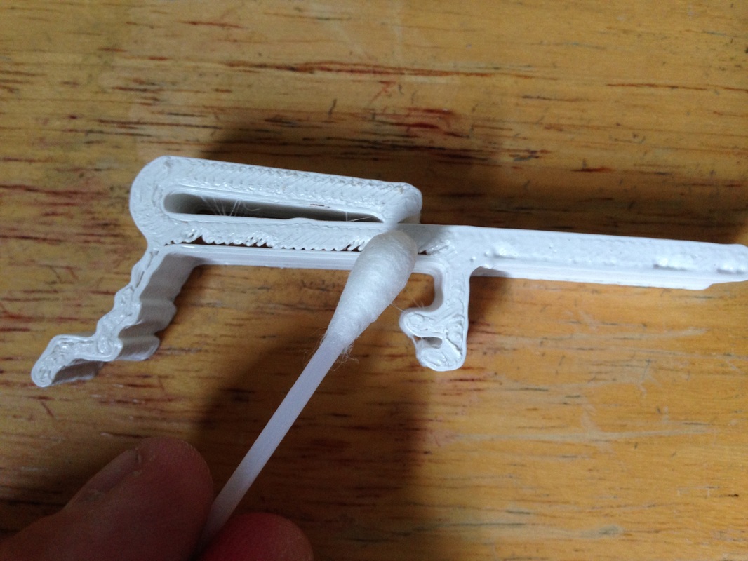
It's known that Acetone (like the stuff sold for nail polish removal) can soften the top layer of a 3D print and help smooth it out but I wondered how well it would melt two plastics together. So I dipped a cue tip into the acetone and started rubbing on the edge while pushing toward the gap. It didn't take long to see the improvement in the look of the clip. The gap started to disappear.
|
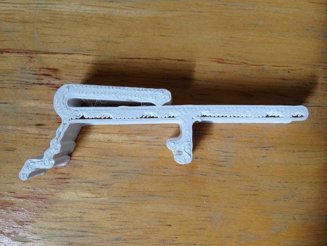
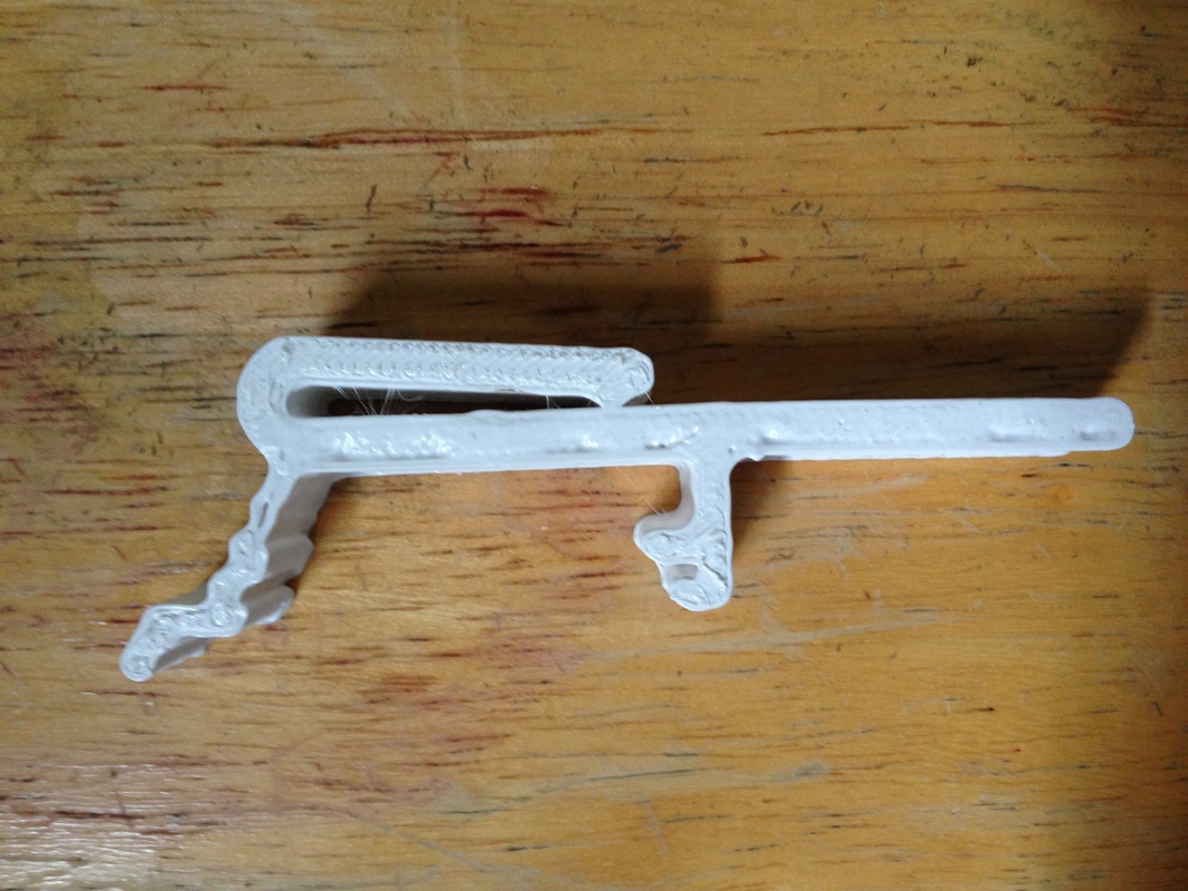
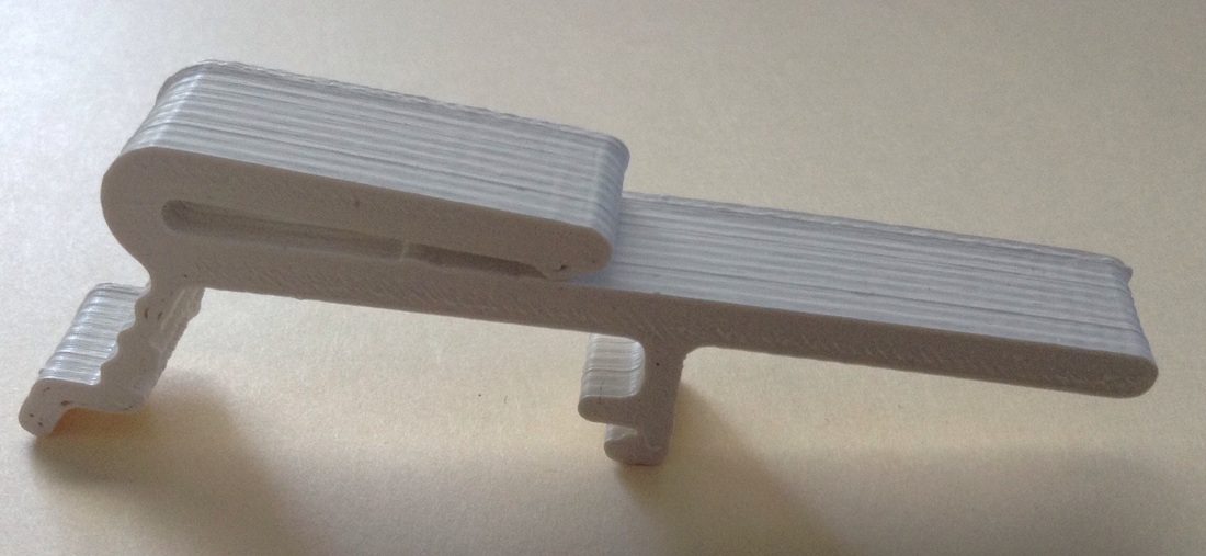
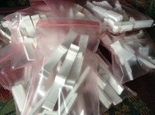
I tried to print some plastic clips with the fastest settings using 0.4 mm height and 10% fill. I also ran the head at the highest speed. The prints came out better than I expected and its a great way to get a prototype print out fast but one drawback is the quality (as you would expect when cutting corners). The picture above left shows the results. The clip had all the key dimensions but the top side of the print had gaps between the outer ring and the inner fill. It affected the clip when snapped in place. The bottom side wall and the inner fill would separate slightly and affect the clips ability to snap in place. So rather than pitch them I tried an experiment. It's known that Acetone (like the stuff sold for nail polish removal) can soften the top layer of a 3D print and help smooth it out but I wondered how well it would melt two plastics together. So I dipped a cue tip into the acetone and started rubbing on the edge while pushing toward the gap. It didn't take long to see the improvement in the look of the clip. The gap started to disappear. A little more rubbing and the edge began to to look filled. The real test can when flexing the clip, and the Acetone did the trick. The clip was much stronger and flexed as expected when snapped in place. The inner and outer plastic had fused together quite well. The clip was obviously stronger and looked better too. I had another print that had split on one of the layers so I applied a little Acetone between the layers and they fused together as if they were never apart. I've heard of people printing pieces of a larger object and then using Acetone to glue them together. Now I understand how well that works. The Davinci 3D printer can print a 7.8" x 7.8" x 7.8" object but now with this Acetone fusing I can print something much bigger.
0 Comments
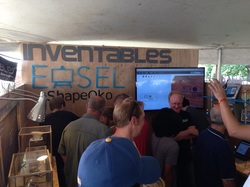
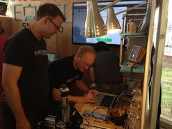
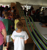
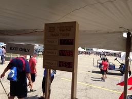
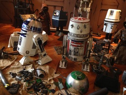
I didn't have a booth MakerFaire - Detroit this year but, I spent the first day of the Faire checking things out. It's actually the first time I got to roam the place without having to rush back to my booth so its really the first time I've been able to enjoy everything MakerFaire - Detroit has to offer. My first major find was the guys from Easel. They produced a CNC drawing software that handles all the GCode creation as well, plus it sends it to a Shapeoko CNC cutter, all in one software application. And it's Free! They basically created for CNC cutting what TinkerCad does for 3D printing and more. I thought it was still in Beta mode but it has apparently been officially released per the Easel guys. And who was there checking it out at the same time I was? None other than Ben Heckendorn of the Ben Heck show. We were both bombarding them with questions but Ben got to try it out first so I just watched. It's really awesome. I plan to add a Shapeoko to my lab so I'll have both 3D printing and CNC capability. They were routing out a circuit board when I first walked up. At my 3rd MakerFaire in 2012, I had a Hot Wheels multi-lane track with a custom LED winner indicator at the finish. It had light sensors built into the track and would light an LED for the winner. It was a hit with the kids. Well I saw a new one at this years Faire that blew mine away. It used wooden cars and had timers for each lane. It was huge and extremely popular with the kids. It was built at the Maker Works makerspace in Ann Arbor Michigan but unfortunately it was so crowded I couldn't get any details on who made it or the electronics used inside. And finally, what would a trip to Maker Faire - Detroit be without a visit to the Star Wars booth. Every year they step it up. Storm Troopers as usual along with a Droid junk yard. I tried to get through everything at the Faire, which included so many 3D printers. There was just about every kind you could imagine, except for the Davinci 3D. I didn't see a single Davinci 3D printer (unless someone was hiding in a corner). I even talked to a few people about the Davinci and found many knew nothing about it. But I did get to compare the prints of all various printers and it was clear to me that the Davinci prints just as good as most of the printers costing far more.
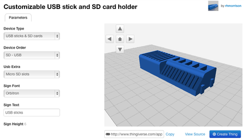
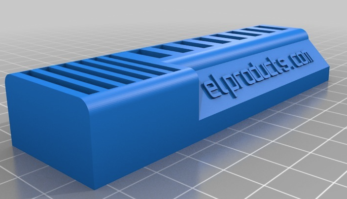
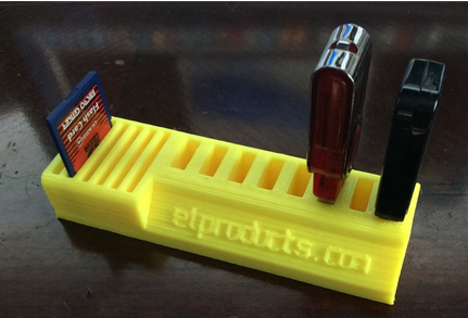
3D printers have clearly taken over the Maker Faire. What was interesting is I saw very few electronics booths or Arduino booths other than the big Make Magazine tent. It appears that most of the electronics sellers with custom shields and boards that were at past Faires have either quit Maker Faire - Detroit or got sick of competing with the Make Tent. That is a shame because the first few years you could find just about any electronics you wanted. Raspberry PI was at a few booths but they were just showing something it could do. Arduino presence was not big either outside the Make Tent. Overall, I thought it was another great Maker Faire - Detroit. Outside the weather was hot but perfect. Inside the museum was cool and crowded. The fact that it's actually in Dearborn, not Detroit, at The Henry Ford and costs $28 to get in for the day makes it the most expensive Maker Faire I know of. But people still crowd the place. I continue to be amazed by the crowds that this Faire draws. It is well worth the trip if you get a chance. I often use TinkerCad for designing my 3D projects but recently found out that Thingiverse, which is a library of open source 3D designs, has a feature called Customizer. I don't know all the details on how it works but I don't need to know because it makes modifying an existing design incredibly simple. I saw a USB/SD card holder on a YouTube video from a poster named Barnacules. He modified it to make it a custom size. I found the design on Thingiverse by rhmorrison and the site had a link to the customizer that brought up the screen above. Through drop down menus I could easily change the design. When it was done I clicked on "Create Thing" button and a few minutes later the .stl file was ready for download. I added more USB Flash Drive slots and reduced the number of SD card slots. I added my domain name to the front and removed the tabs on the side for connecting a couple of these together. The final design is shown above. From there I loaded it into the XYZ Printing Software and sent it to my Davinci 3D Printer. I used a low resolution 0.4 mm setting so I could print it quicker. I didn't need precision but it turned out great. The lettering on the front is a little sketchy but the drives fit good and so does the SD card. I don't know how many designs offer this Customizer option but from what I could tell its still rather new. I did find an iPhone case you could modify and a flat sign you could change the words on. Check it out and let me know what you did with the Customizer.
Back in the beginning of June, I wrote a blog post about how I scanned a Vertical Blind Valence Clip on my paper scanner and then imported into TinkerCad to produce a 3D reproduction. Well it got the attention of an online company that ordered 30 sets of 5 clips. They plan to sell them on Amazon. I would really like to have a second Davinci running prints but that will have to be financed from the first one. I'm hoping this will help. It was not a quick process. I had to make a file that included 6 clips per session which was the most I could fit on the platform and still have some space. The print would take about 2 hours so I would run it around the clock including at night. On some occasions the print would get messed up and I'd wake to a massive ball of thin plastic strings. It was strange because the next print would run fine. Clearly, a 3D printer is not made for mass production but I completed the task and shipped the clips. Hopefully they sell well enough that I get a second order. It may take some time but the Davinci 3D printer may not be just printing plastic, it may be printing the means to a second printer.
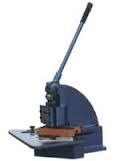
I saw discussion recently where people were showing how they cut out their circuit boards. I've used a Sheet Metal Notcher for years to cut my boards. It allows me to use the $59 ExpressPCB prototype service to multi-panel designs and then easily slice them apart with a Sheet Metal Notcher. The notcher has a strong blade that cuts a perfectly straight line in the board. I use the silkscreen to mark where the cuts need to be. I line up the cut and pull the lever for a easy slice of the board. I made a mount for the notcher in my workshop and placed a plastic bucket at the bottom to catch the boards being cut. Watch the video below for a demonstration of cutting a multi-panel board. I've since found Copper Connection and ITEAD studios are very useful for getting the gerber files and then producing them for less mone but this notcher is still useful because ITEAD doesn't offer v-score so for prototype runs I can still use my notcher to cut out the boards.
Amazon put my book "Beginner's Guide to Embedded C Programming" on sale with free shipping for Prime members at a price that is cheaper than I can sell my own book. So if you were considering buying this book, I would grab it now because I don't expect this sale to last long. I get the same royalty either way so it doesn't hurt me if you pay less so I encourage you to save money and learn Embedded C Programming. Click on the picture below and it will take you right to it. I really don't know how they can sell it this cheap but I'm sure they have a plan. The book is getting bit older but its still very relevant. And all the software tools I use and the hardware can still be downloaded or purchased from Microchip or Digikey.
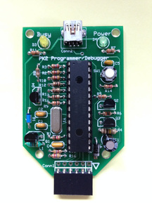
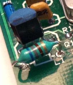
All the source code and the MPLAB IDE with built in HI-TECH C compiler can be downloaded from the link on my cbookfiles page. The PICkit 2 Starter kit I use in the book is in stock at Digikey. Honestly, I'd love to sell you my book from my website as the book sales help fund everything I do here at elproducts.com but I cannot beat this deal. I discount my book at this my site to help those getting started but Amazon is blowing that discount away. Get it while it lasts. I recently received a message from a reader of this blog that had tried to build a version of my PK2 PICkit 2 clone programmer around a PIC18F4550 (40-pin) instead of the PIC18F2550 (28-pin). They were getting a Vpp Voltage Error when powered up and connected to the PICkit 2 software. Turns out I had the same issue on one of my custom designs that had the PK2 built into it. I had tried to figure out the cause of the error and found I had grabbed the wrong resistors for the base of the Q2 and Q4 transistors. What should have been 10k (brown-black-orange) were actually 300 ohms (orange-black-brown). So I replaced them but not before replacing the L1 inductor and the C1 47uf capacitor. The resistors were definitely wrong but after replacing them I still couldn't get it to work so in frustration, I set it aside. Then when I got the message through my contact form asking me about the Vpp Voltage Error I decided to pull mine out and do some debugging again. Only this time I compared it to a working unit. I probed the various points of the working programmer with a probe from my oscilloscope and saw that the Vpp voltage on both sides of the L1 inductor were 5 volts at idle. I remembered seeing a lower voltage on one side of the inductor in previous tests of the failed unit so I probed it again and found that the L1 inductor had 5 volts on only one side. So even though I had replaced it, it was not working as expected. I disconnected everything connected to the dead side and still the voltage was zero. This told me nothing was shorting the inductor to ground as I thought may have been happening. Could I have replaced an inductor with a bad inductor and created a new problem in addition to the wrong resistors? I decided to replace it again only this time I didn't fully bend the leads to fit the tight space I had created in the board design. I think I mentioned in the PK2 build blog post that I didn't allow enough spacing for the inductor leads and maybe I bent the leads too much and broke something internal trying to make it fit flat on the board. I removed the old one and then carefully bent the leads of a new inductor to fit the hole spacing in the board but with a relief bend in the lead instead of 90 degrees. This left the inductor sitting off the board but at least the leads weren't bent 90 degrees. A quick plug into the computer USB port and the PICkit 2 software reported everything was working as expected. No more Vpp Voltage Error. I now had voltage on both sides of the inductor.
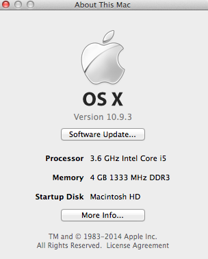
So take this as a lesson if you build the PK2 design, make sure the inductor is not bent too tight to break the inner wire. Apparently some of them are very fragile. I will fix the layout in the future so this problem doesn't happen again. I sent the reader an email describing this but have yet to hear if it was their problem as well. I decided to share this with everybody in case anybody else has one of these sitting around with a Vpp Voltage Error. I finally replaced my 2006 iMac with an i5 unit I bought on EBAY. I've found the best way to buy Apple computers is used and typically EBAY has the best selection and best price. People tend to care of their Mac computers and unlike PCs, Macs don't have to be refreshed every 2-3 yrs to make them work again. At least that's been my experience. I've been wanting a new iMac for a couple years but couldn't justify the expense because my 2006 is still running good. But its a core duo and I need a core 2 duo or newer to run some of the latest software. I can't run Microchip's MPLAB X for developing PIC® code and my Davinci 3D printer software required OSX 10.8 and 64 bit processor which the core duo is not. I've also been using cloud type applications such as TinkerCad for creating 3D objects and MakerCase for 2D objects and they weren't running all that well on the core duo machine. So I went shopping. I wanted to see if I could get an i3 version for under $600 but kept finding machines with issues or didn't have all the features I wanted. So I looked at the i5 machines to see how much more they would cost. That's when I saw my computer. An i5 running at 3.6 GHz. I would have preferred more RAM than 4 GB but other than that the machine looked perfect and at $649 with free shipping it was as close as I figured I was gonna get. The reseller had good ratings and I read some of the feedback and it was all good. I showed my son who is our local Mac expert and he said he would buy it if I didn't. So I'm writing this on my new iMac. I've installed MPLAB X and the XYZ Printing software for the Davinci 3D. MPLAB X is working great. I had problems with the XYZ software as it kept locking up but I contacted their tech support through email and they sent me a new version which is working fine.
The old iMac? No it's not going up for sale on EBAY. It's now in my lab as it has Parallels installed with Windows XP and I use that for creating circuit boards and writing Great Cow Basic and PICBASIC PRO code for PICs. And the Mac portion still runs many programs just fine. So it will live on in the lab. |
Categories
All
Visit previous blog posts in the archives below.
Archives
February 2018
About ChuckChuck has been programming with PIC Microcontrollers since there were only five devices. Now there are over 700 and growing. He also has a lot of fun 3D printing designs using his Davinci 3D printer and TinkerCad software. In this series of blog posts and occasional videos on his YouTube Channel he tries to help you get started with electronics and 3D printing. Disclaimer |


 RSS Feed
