|
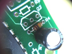
In my last blog I asked for help with finding a lower profile capacitor for my PK2 programmer. The 47uf 25v part I was using was 11 mm tall. I wanted it no larger than 7mm tall but preferred to keep it the same diameter but couldn't find one that fit the requirements. On a tip from a reader I decided to try a 6.3 mm x 7mm cap that was on Digikey's online catalog under part number P834-ND. I measured it up and it was gonna be close so I ordered some. The order came quick as it usually does from Digikey and the results are in. The cap is a success. It fits in the location without interfering with the neighboring resistor. The height is perfect as it remains one of the tallest parts on the board but no higher than the PIC18F2550 in a socket. So now I can get to work on a top and bottom plastic shield to encase the programmer. I also had mentioned that the spacing for the inductor L1 was off, but I realized I hadn't bend the leads tight enough. If I bent them straight down off the plastic casing then the leads fit perfectly in the board. So the PK2 design is complete. Next step is the plastic case.
0 Comments
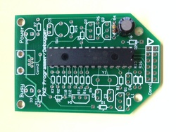
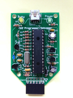
I finally found some time to build up one of the new PICkit 2 clone boards I had made at ITEAD studio. It was almost a month ago that I posted about receiving the boards. They had been sitting on my desk begging to be tested but I was so busy with other projects, including my latest Kickstarter, that I had to keep putting it off. The good news is the test was successful. The board worked as expected. One minor issue involved the L1 inductor. The spacing was off just a bit so the lead had to be bent back a little. I used a different inductor on the previous design and didn't double check the spacing on the new one. So I'll just adjust it on the next version. The smaller type B connector is a leaded design rather than the typical surface mount. I used leaded so it could be easily soldered as a kit. But the leads on the connector are so short and so close together I would say its only slightly easier to solder than surface mount. I made the change based on several comments from people that they preferred the smaller connector vs the original larger type A. I made the change but I'm not sure its any better. I'll probably offer both versions on the website so you can choose your own option. I'd like to design a nice plastic case even if its just a top and bottom with open sides. The biggest hang-up is the 47uf 25v cap. I have searched all over for a low profile version but the shortest I can find is the 11mm tall version without going to a very large diameter. I may have to switch to a tantalum cap but that will be far more expensive which I don't want. If you know of a low profile (7mm or less) with a 5mm diameter, let me know via email. I would appreciate it. With the new lower profile USB connector, the cap stands up like an antenna. I thought about laying it down but there isn't any room on the board for that without moving everything up. So I'll just keep searching.
My first book; Programming PIC Microcontrollers with PICBASIC was written about using the PICBASIC and PICBASIC Pro Compiler from microEngineering Labs. It's a BASIC compiler for Microchip PIC MCU's if you aren't familiar with it. I've been using the compiler since it was first released. Along the way I asked many times for a free version so I could use it in books and reference for readers, even if the version was limited to one device. They listened and would occasionally throw me a bone. At first I had a version that only worked with the PIC16F84A but that didn't last. Then eventually a sample version was released and I used that in my book "Programming PICs in BASIC" which is my second book to use PICBASIC. Then a few years back they released the new PBP3 version and the sample version became a 15 day evaluation version which I hate. Beginner's need more time and 15 days is not enough to evaluate a compiler. Well, the good news is the PBP3 Student Edition is now a free download. You have to go through their purchasing process but in the end no credit card is needed just a registration and you get an email with the download link and the registration key to enable it. The Student version has two limitations, its for non-commercial use and it only supports the 12F683, 16F688, 16F690, 16F88, 16F886, 16F1937, 18F25K20, 18F25K22 and 18F2550 but thats it. It doesn't expire and doesn't limit you to memory size. Its a full blown compiler to learn programming with. Now the non commercial limit shouldn't be a big deal since most beginner's or hobbyists are only learning anyway. But if you were to come up with some great design, the Gold Version of PBP3 is $279.95 and gives you full commercial use. And that should pay for itself in the first batch of sales. And your code will build without issue cause the Student Version and Gold version use the same syntax, just a lot more parts supported. The list of parts may look familiar. They are the same list I use in all my elproducts.com influenced designs such as the CHIPAXE and CHIPINO modules. There are even a few extra. The list gives you a part in 8 pin, 14 pin, 18 pin, 20 pin, 28 pin and 40 pin package. Plus you get a couple larger memory 18F parts. So to say this is limiting is not really understanding what they gave us. So I tip my hat to the guys at microEngineering Labs for doing this. I plan to include it in future articles and possibly more books. And the MCStudio IDE that installs with it is a great IDE as well. I cover how to install it and use it with the PICkit 2 in my Programming PICs in BASIC book so it fits well with my Build Your Own PICkit 2 project. When I started out, a cheap programmer was $200 and a compiler was in the thousands. So to see how far this has come to make it easier and cheaper for the hobbyist/hacker/maker/basement engineer is just amazing. So enjoy the new PBP3. And tell them I sent you.
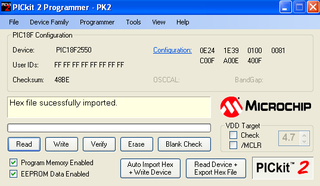
If you are a returning reader of this blog, then you will probably notice the updated style of the website. I wanted to make it cleaner looking and change some of the coloring to be more appealing. It also allowed me to move things around a little. Not a big change but I really like it. Hope you do too. I was asked by a reader if the PICKit 2 firmware configuration settings were available. This is for the Build Your Own PICkit 2 project on my site. The firmware that gets programmed into the PIC18F2550 at the heart of the PICkit 2 is a .hex file that has the configuration settings encoded in. I plan to expand on my Understanding Hex Files page to add an explanation for how this is done but for now I figured I would just add the configuration settings on the PICkit 2 page. The settings are shown in the upper right hand corner of the picture above. I captured this from the PICkit 2 software. So I took an existing PICkit 2 clone and connected it to a CHIPINO module. Then installed a PIC18F2550 into the CHIPINO socket. The PICkit 2 sensed the PIC18F2550. Then I loaded the pk2v023200.hex file and the configuration was automatically loaded into the software. It shows the hex values for each Configuration register and there are more than one on the PIC18F2550. If you click on the blue Configuration word shown in the picture above, a new screen will pop up with even more detail. I show that expanded screen shot on the Build Your Own PICkit 2 page (which is what I added recently per this post). Hopefully this will help anybody else that may need those settings when trying to build their own PICkit 2.
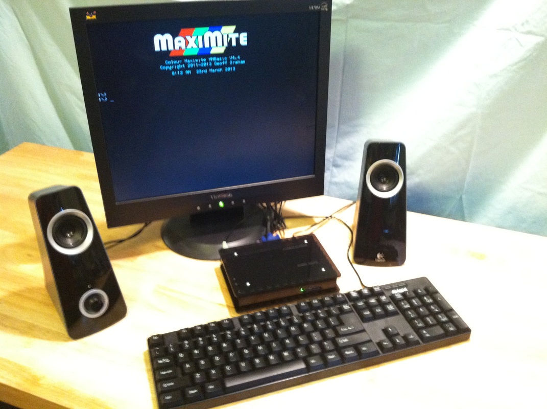
Another one of my Kickstarter campaigns, this time the Maximite BBX BASIC Language Computer, recently completed and was successful. I knew this would be a tough one so I ran it for 60 days instead of the normal 30. The project is based on the open source Maximite Computer design by Geoff Graham. My main goal was to create a beginner's book on programming in the old fashion BASIC language that I learned programming with and see if there was enough interest in the idea. I needed 100 backers to basically break-even on the project and 100 is what I got. The Maximite is a great platform for the book and no computer is needed if you have the Maximite. It is the computer. There are existing Maximite boards and kits available but I wanted a complete package with a plastic or wood case to protect the electronics from young hands but also allow access to the Arduino headers and Electrical ports for expansion. These I/O features allow me the chance to introduce embedded style programming as well. Thankfully the project was successful and now I'm working with some of the suppliers to deliver the rewards and the biggest task is finishing the book/manual. In it I introduce programming at the entry level and then expand it out with a several key projects. If this goes over well then I can follow-up with more project style books. I'm looking at open sourcing a lot of the info so others can share in the fun. Some may say this is a waste of time because there is Arduino and Raspberry PI that can do a lot more. But typically "Lot More" also means "Lot More" complicated. And since I'm all about the beginner, I feel starting with the BASIC language is still one of the best paths to success. There are also a lot of people trying to recreate this BASIC style programming on the Raspberry PI so why not have a dedicated option.
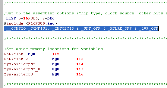
I also know there are a lot of "old timers" like me who still appreciate the old style BASIC programming and the Maximite BBX brings that back with a modern twist. I already have a separate website setup for the Maximite BBX which I plan to link in to this site's menu and then expand it for the future. Stay tuned for more info about the BBX in the future. When programming a Microchip PIC you will need to setup the configuration settings. These are the settings that control which oscillator to use, internal or external, high speed (>4Mhz) or low speed (<4 mhz). The MCLR reset pin can be an external reset pin or a standard input pin. The watchdog timer can be enabled or disabled. Low voltage programming (which a lot people get caught by) can be turned on or off. All these and more are in the configuration settings. Most devices have default settings and then the compiler you are using will probably have some default settings as well. The Great Cow Basic compiler I like to play with, has default settings based on the speed you are running and what device you are programming. In the end the assembly file produced will have a line that starts with __CONFIG ... and then all the settings. Sometimes this will occur on multiple lines. But in the end all that data ends up in the .hex file you program the Microchip PIC device with. When you load the .hex file into the PICkit 2 programmer software, it will automatically load the configuration settings from the .hex file. You can then manually change them if you want. Some programmers default to manual setting but most have the option to read them from the .hex file.
Configuration settings can be some of the most confusing parts of programming Microchip PICs for a beginner and that's why I like the way the Great Cow Basic compiler handles all that for you. To really understand all the configuration settings for a device you have to read the data sheet and I won't go into that this time, I'll save that for another blog post. The more complicated the device is the more configuration settings it will have. So that's why its typically not the best move for a beginner to start out with the latest and greatest Microchip PIC device. Its why I recommend the PIC16F690 or the PIC12F683 which I used in a couple of my books. The PIC16F886 is also fairly simple when is comes to the Configuration setup. So don't be intimidated by the Config settings, just learn the basics before you program. I plan to add a section to my website on this topic in the future. Until then if you have a question about programming or config settings shoot me the question through my contact form and I'll try to help you out. |
Categories
All
Visit previous blog posts in the archives below.
Archives
February 2018
About ChuckChuck has been programming with PIC Microcontrollers since there were only five devices. Now there are over 700 and growing. He also has a lot of fun 3D printing designs using his Davinci 3D printer and TinkerCad software. In this series of blog posts and occasional videos on his YouTube Channel he tries to help you get started with electronics and 3D printing. Disclaimer |
- Books
- Chuck's Blog
- YouTube Channel
- About Chuck
- 3D Printing
- Getting Started with PICs
- Build Your Own PICKit 2
- CHIPINO
- CHIPAXE Breadboard Modules
- Understanding Hex Files
- chipKIT
- Newsletter Archive
- Contact
- Retired Designs
- Downloads
- Kickstarter Projects
- Great Cow Basic Site
- Buy Hardware
- Links I Recommend


 RSS Feed
