The kit has a lot of steps and it's not really a beginner kit but I was able to get it together and cut my first piece of wood. I had several mis-attempts because I had not setup the GRBL software properly. Inventables gave me the tip to check the settings and I found the error.
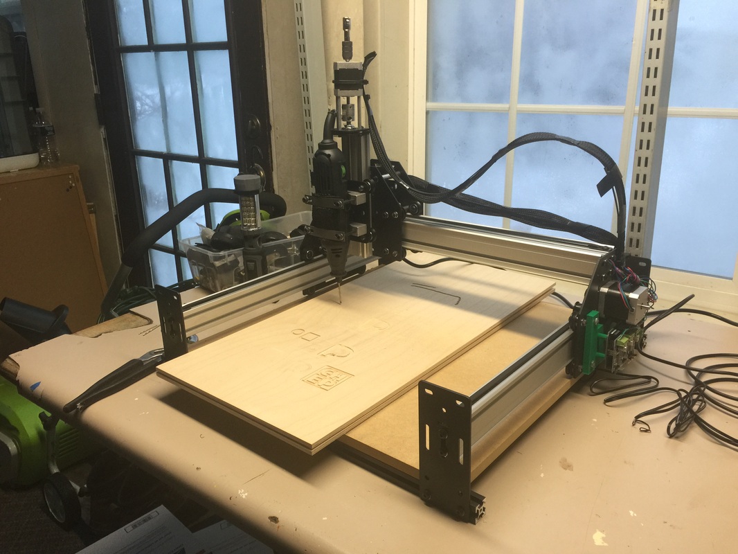
It's been a while since I updated my blog. I've been very busy in my shop and my YouTube Channel continues to grow approaching 1000 subscribers. During all this I was able to put in the hours needed to complete my Shapeoko 2 that I purchased around Christmas. There was a $100 off sale and I bought one. The kit has a lot of steps and it's not really a beginner kit but I was able to get it together and cut my first piece of wood. I had several mis-attempts because I had not setup the GRBL software properly. Inventables gave me the tip to check the settings and I found the error. 
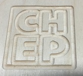
I was finally able to cut out my new CHEP logo and it did a fine job. I need to make a visit to Harbor Freight tools to see what bits I can get for this thing. I want to get some small blade bits so I will be able to cut out circuit boards. My goal is to find a way to cut out 2 layer boards from ExpressPCB files. I can get the gerbers through CopperConnection and then I'll try to find a Gerber to G-Code converter. I know it exists but I just haven't put the time to fully investigate the steps plus I didn't have the the CNC tool to test it all out until now. Learning to cut circuit boards is just one thing on my list of things to do. 
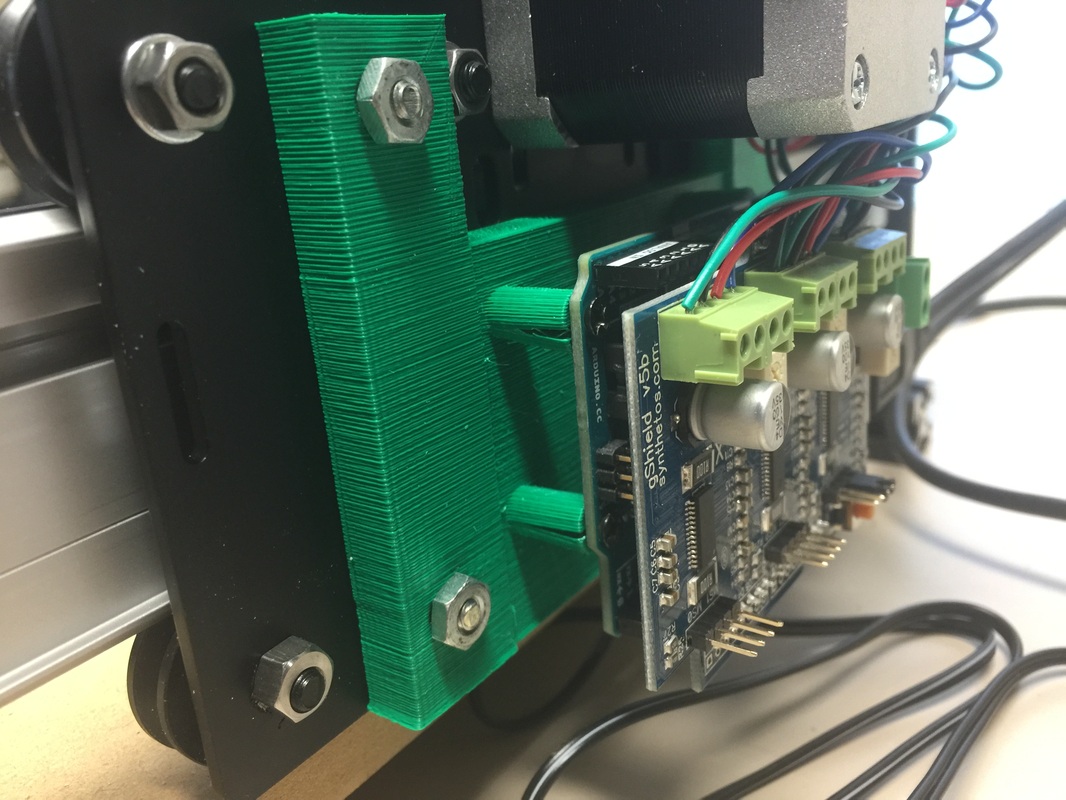
I also 3D printed a base to mount the Arduino board to the frame. If you look close you can see that the mounting bosses split. I have a fix I want to try so that will be part of a future YouTube video. If you have one of these Shapeoko's and have some tips for me, I'm all ears.
1 Comment
For Christmas I bought myself a Shapeoko 2 CNC machine. I'm still waiting for it to arrive but my own CNC machine is something I've been dreaming about for a long time. I've watched CNC machines come down in price and thought about getting a cheap Chinese-built unit on EBAY but the software was always the hangup. They all seemed to use Mach 3 software which required a computer with a parallel port. I had two computers that fit the requirement but they both crashed in the past year so I preferred to get a USB controlled unit. I also wanted an easy software for creating the design. When the Inventables.com guys released the Easel software that also controlled their Shapeoko 2 CNC kit, I was sold. I saw them at the Detroit MakerFaire and saw the Easel software in action. I wrote about it in aprevious post. Well over the holiday, I saw the Shapeoko 2 was on sale for $100 off. This is because the new Shapeoko 3 was coming out soon. Shapeoko 2 had everything I wanted so I bought it while on sale. I received an email that my package was shipped and they are in Chicago and I'm outside Detroit so it shouldn't take long to get here. I'm told it takes about 10-12 hours to put it all together so I'll be doing that over a period of time. I also plan to time lapse record it for my YouTube channel. To get a CNC machine with software for around $550 is something I hoped I'd see but never thought it would happen this soon. I plan to build things that my 3D printer can't and find ways to combine CNC, 3D prints and Electronics to make some interesting projects. I just wish I had more time to play with all these great tools.
And best of all, if you have been following me for a while, you know I'm a really fan of 8-bit microcontrollers. I prefer PICs but most of all I prefer the simplicity of 8-bit. I've had people tell me that I'm crazy for not switching over to 32 bit but I'm still not convinced I need that extra horsepower for what I like to do; build electronic products. Well my 3D printer is 8-bit, and now so is my Arduino controlled CNC Shapeoko 2. Not to mention my lab full of 8-bit PIC boards and projects. Tell me again why I need to switch to 32 bit? I've always wanted a low cost way to program PICs and a tablet seemed like a great solution. But most tablets either didn't have a USB port for the programmer or ran an operating system that didn't support the software tools I like to use such as Great Cow Basic and PICkit 2 software. Then I found the Winbook tablets at Microcenter. They offer a very low cost tablet that runs a full version of Windows 8.1 and has as full size USB port. On the smaller ones they are a USB 2.0 and on the larger versions they offer USB 3.0. The pre-Christmas deals offered the smallest 7" Winbook for $59.95. It included Windows 8.1, 16GB of Flash Storage and 1GB of RAM. It also has wireless-N and a micro-HDMI port. So I bought one and downloaded the Great Cow Basic IDE at my Greatcowbasic.com site. I then ran the software without issue. The next step was to test the PICkit 2 on the USB port. This worked smoothly as the GCB IDE has the PICkit 2 command line interface built in. The programmer launched and programmed a PIC16F886 on a CHIPINO module without issue. I did find that 8GB of the 16GB was taken up by the operating system and other features so the memory size is limited, but plenty for what I was doing, at least I thought so. Then I decided to see if the Davinci 3D printer software, XYZware, would run on it. I downloaded that and it ran fine. I could load a 3D print into my Davinci without issues and the print was launched. My next step was to try and install the ExpressPCB software I like to use for creating circuit boards. Before I did that, I decided I needed a keyboard and mouse first. I tried a bluetooth keyboard but I couldn't it them to connect so I used a USB expander and was able to connect the PICkit 2, USB Keyboard and USB mouse to the tablet and everything worked great. I also wanted to to see if I could load Chrome on the tablet so I could modify Tinkercad designs but I found the memory usage was already getting low. Seems that Windows did an update and used up a bunch of space. I have to figure out what I can do to get some of that back but my idea of installing ExpressPCB may not be possible either. I guess 16GB isn't enough space. The 32GB is $139.95 but as the price gets higher I may just stick with a low cost laptop. The tablet has a microSD card slot so I'm going to try and load the programs on there and see if I can run everything from the SD card. So I've achieved one goal of programming PICs with a tablet but to create designs, write the software, send the 3D print file for a complete design from a tablet will require more memory with the SD card if that works or spend more money on a larger tablet which is not what I want to do. But at least I know its possible at the simplest of all levels. I can write a Great Cow Basic program and program a CHIPINO module with the code. Not bad at all for $59.95.
A reader of this blog, Frans Stevens, pointed out that the schematic for my Build Your Own PICkit 2 schematic had an error. The USB connections to D+ and D- were backward. I quickly looked over the schematic and also the PCB layout because I've built many of these and they all worked. But I found out he was right, the schematic was wrong. Luckily the PCB was correct and that is why all my PK2 programmers work fine. Pin 2 of the USB needs to connect to D- and pin 3 needs to connect to D+. I had them backwards in the schematic. So I immediately updated the schematic and uploaded to the Build Your Own PICkit 2 page. Its awesome to have such supportive readers with the willingness to share any errors they find. I want my information to be accurate but I'm human and do make mistakes. Thanks Frans. I had a little bit of free time after the Thanksgiving Holiday so I created a few 3D printer projects. One was an Advent Calendar Christmas Tree. This took all the space my Davinic 3D printer could support and took two print runs to finish it. The blocks slide out and can be flipped so the number is hidden. Everyday you take one number and flip it until only #1 is left and that is Christmas Eve. The design was done in Tinkercad and the full build is shown on my YouTube Channel and in the video below. I did it as a count-down to 1 but you can reverse the blocks and make it show the calendar day so place the #1 in the bottom and the #24 at the top. The blocks slide out easily and can be pushed from the back. At some point I could print one of these and put LEDs on the blocks so a Microcontroller can do the count-down automatically. All the files are open source on Tinkercad and the .stl's are available at Thingiverse. I've returned as a columnist for Nuts & Volts Magazine. My column titled "Getting Started with 3D Printing" started today in the December issue of Nuts and Volts Magazine. I wrote the "Getting Started with PICs" column from 2006 thru 2009 and it ended for reasons beyond my control but I'm happy to be back. The idea behind the column is to help anybody just getting started with 3D printing with tips and tricks that I've learned or will soon learn as I get deeper into 3D printing myself. There is so much to learn beyond downloading a thingiverse file and printing it. And with the various low cost printers available, I thought the timing was right to help others get started. If you are a regular reader of this blog though, you know I've been writing about my 3D printer adventures for some time. But the N&V column is written for the electronics hobbyist who wants to design that custom case or special mount for their electronic project. There is so much 3D printing can offer and I feel like it's just getting started. Reminds me of the early days of the PC. I think we are still waiting for that killer app or killer print that will make everybody want a 3D printer the same way Visicalc did for the early PCs. I've also added some new videos to my YouTube Channel that weren't posted here. I'm trying to separate this blog and the YouTube Channel a bit because I still want to help those who still are looking for my help with their electronics hobby. If you are a subscriber to N&V then check out the column. If not, maybe find it on the newsstand and see if it something you'd like to read. I hope to keep that column running for a long time.
I recently bought a CLOUDBIT kit from littleBits and it's expected to arrive in a few days. What interested me the most is the application they advertise for a doorbell switch that will send you a text message when the switch is pressed. The idea is to indicate someone is at your door even if you aren't home at the time. I found this idea interesting because there are so many projects where I'd like to receive a text message indicating something timed out or a process completed. That way I don't have to sit and monitor it or check back often. One such process is 3D prints. When a print is done I'd like to receive a text message letting me know. I've read about multiple different modules that allow you to connect to the internet but I found most of them very confusing. That was until I found littleBits. The module has a linux computer on-board so this is more than just a little plug and play module, it's a very complicated module that reduces the internet access down to a high/low signal.
The module relies on an internet service called IFTTT which stands for If That Then This. I've visited the site and it appears to be some kind of scripting language setup that allows you to easily create actions based on various inputs and outputs all connected through the internet. I hope to understand it a lot better when I get the CLOUDBIT running on my Davinci 3D printer so stay tuned if you have any interest in this type of project. In the Make Magazine November 2012 issue, they ran a 3D print competition with many of the existing available 3D printers. They ran a test print that had some unique features. It had an unsupported arch, round and hex holes, posts and a box with walls of different thickness. Then each printer created it at default settings. I decided to try the same print on my Davinci 3D printer and the results were great. I printed with and without supports so the arch failed in the non-support but everything else was fine. It's still not clear to me if support would have been permitted or not. I produced a YouTube video showing the steps and the results. The .STL file is available on Thingiverse for anybody to try. I printed it at different levels or 0.2 layer and 0.4 layer. The default on my XYZware is 0.4 layer, 10% fill and standard shell and standard speed. The support was low fill. Both the 0.2 and 0.4 looked great. It's true that the Davinci had two years of development over the printers in the magazine, since it wasn't released until two years later, but a sub $500 printer wasn't available back then either. So I'm once again sold on the quality of this Davinci printer. I found a really interesting 3D print file of a single-print hinged box. Not two pieces snapped together, but rather a single print. The design was created by a user name anewsome on thingiverse. The design prints both halves of the hinge together so the 3D printer needs to be able to print very tight tolerances. The question was, would my Davinci 1.0 3D printer be up to the challenge. I've fixed a few flaws on my printer such as a broken bearing and a wobbly base. With that my 3D prints were coming out excellent. So my guess was the Davinci could deliver and it did. The video above from my YouTube Channel shows the steps to create the hinged box. This just shows that a low cost 3D printer can deliver as well as the higher priced units. It also shows you don't need to hack the hardware or software to get great results.
In my book Programming the BASIC Atom Microcontroller and also in my book Getting Started with PIC's - Volume 2, I wrote about creating large characters on a 4x20 LCD. It was also printed in the 2007 September issue of Nuts & Volts Magazine for my column Getting Started with PICs that ran from 2006 thru 2009. I used the trick of creating custom characters on the first 8 locations of the Character RAM in the LCD HD44780 driver chip to build the large digits. The topic of creating custom characters came up recently on the Great Cow Basic forum so I thought I would repost the article here on my website under the download page. It was written to run on the Basic Atom microcontroller but the concepts and description in the article explain how to create the effect, so it should be easy to adapt it to any microcontroller. I know I've done it with PICBASIC but I could not find any sample code in the ever expanding list of code samples on my computer. Hopefully this repost of the article will be helpful to somebody out there in my audience. I may repost all the Getting Started with PIC's articles over time as a bonus to my readers. They are a bit dated, but not out of date. So they may be helpful. If you are interested in that, please comment below.
|
Categories
All
Visit previous blog posts in the archives below.
Archives
February 2018
About ChuckChuck has been programming with PIC Microcontrollers since there were only five devices. Now there are over 700 and growing. He also has a lot of fun 3D printing designs using his Davinci 3D printer and TinkerCad software. In this series of blog posts and occasional videos on his YouTube Channel he tries to help you get started with electronics and 3D printing. Disclaimer |