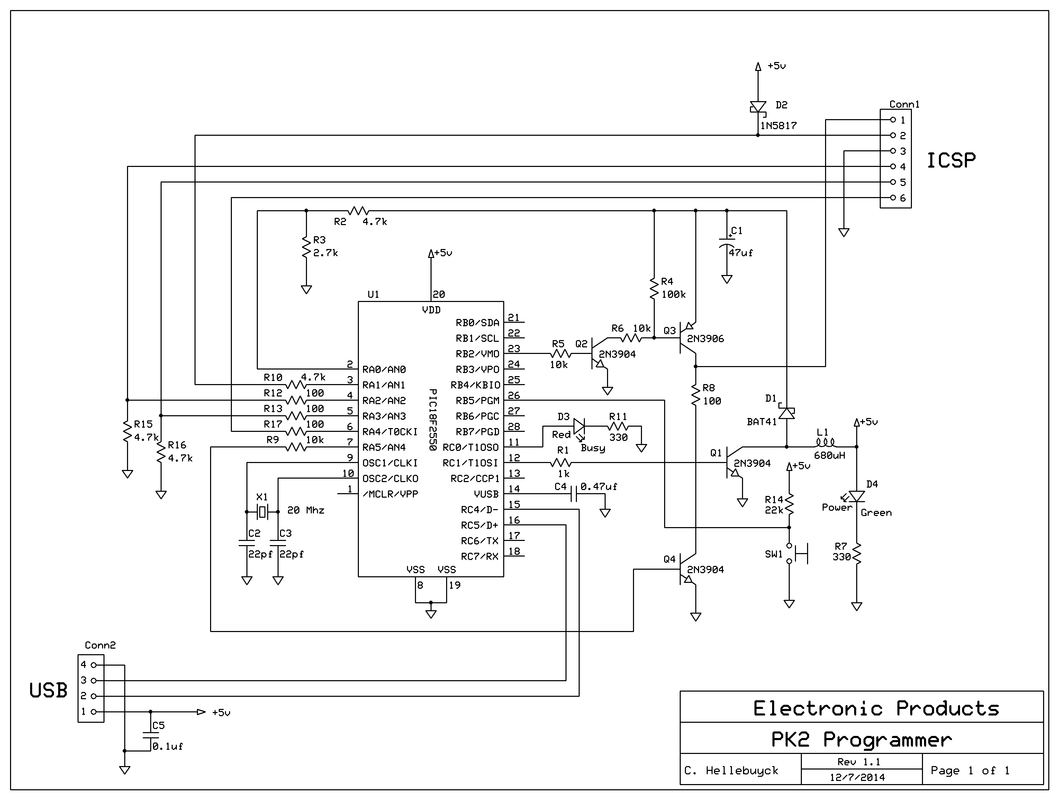
|
A reader of this blog, Frans Stevens, pointed out that the schematic for my Build Your Own PICkit 2 schematic had an error. The USB connections to D+ and D- were backward. I quickly looked over the schematic and also the PCB layout because I've built many of these and they all worked. But I found out he was right, the schematic was wrong. Luckily the PCB was correct and that is why all my PK2 programmers work fine. Pin 2 of the USB needs to connect to D- and pin 3 needs to connect to D+. I had them backwards in the schematic. So I immediately updated the schematic and uploaded to the Build Your Own PICkit 2 page. Its awesome to have such supportive readers with the willingness to share any errors they find. I want my information to be accurate but I'm human and do make mistakes. Thanks Frans.
0 Comments
Leave a Reply. |
Categories
All
Visit previous blog posts in the archives below.
Archives
February 2018
About ChuckChuck has been programming with PIC Microcontrollers since there were only five devices. Now there are over 700 and growing. He also has a lot of fun 3D printing designs using his Davinci 3D printer and TinkerCad software. In this series of blog posts and occasional videos on his YouTube Channel he tries to help you get started with electronics and 3D printing. Disclaimer |
- Books
- Chuck's Blog
- YouTube Channel
- About Chuck
- 3D Printing
- Getting Started with PICs
- Build Your Own PICKit 2
- CHIPINO
- CHIPAXE Breadboard Modules
- Understanding Hex Files
- chipKIT
- Newsletter Archive
- Contact
- Retired Designs
- Downloads
- Kickstarter Projects
- Great Cow Basic Site
- Buy Hardware
- Links I Recommend


 RSS Feed
