
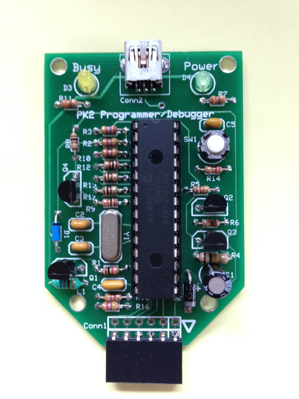
I recently received a message from a reader of this blog that had tried to build a version of my PK2 PICkit 2 clone programmer around a PIC18F4550 (40-pin) instead of the PIC18F2550 (28-pin). They were getting a Vpp Voltage Error when powered up and connected to the PICkit 2 software. Turns out I had the same issue on one of my custom designs that had the PK2 built into it. I had tried to figure out the cause of the error and found I had grabbed the wrong resistors for the base of the Q2 and Q4 transistors. What should have been 10k (brown-black-orange) were actually 300 ohms (orange-black-brown). So I replaced them but not before replacing the L1 inductor and the C1 47uf capacitor.
The resistors were definitely wrong but after replacing them I still couldn't get it to work so in frustration, I set it aside.
Then when I got the message through my contact form asking me about the Vpp Voltage Error I decided to pull mine out and do some debugging again. Only this time I compared it to a working unit. I probed the various points of the working programmer with a probe from my oscilloscope and saw that the Vpp voltage on both sides of the L1 inductor were 5 volts at idle.
I remembered seeing a lower voltage on one side of the inductor in previous tests of the failed unit so I probed it again and found that the L1 inductor had 5 volts on only one side. So even though I had replaced it, it was not working as expected. I disconnected everything connected to the dead side and still the voltage was zero. This told me nothing was shorting the inductor to ground as I thought may have been happening. Could I have replaced an inductor with a bad inductor and created a new problem in addition to the wrong resistors?
I decided to replace it again only this time I didn't fully bend the leads to fit the tight space I had created in the board design. I think I mentioned in the PK2 build blog post that I didn't allow enough spacing for the inductor leads and maybe I bent the leads too much and broke something internal trying to make it fit flat on the board.
I removed the old one and then carefully bent the leads of a new inductor to fit the hole spacing in the board but with a relief bend in the lead instead of 90 degrees. This left the inductor sitting off the board but at least the leads weren't bent 90 degrees.
I removed the old one and then carefully bent the leads of a new inductor to fit the hole spacing in the board but with a relief bend in the lead instead of 90 degrees. This left the inductor sitting off the board but at least the leads weren't bent 90 degrees.
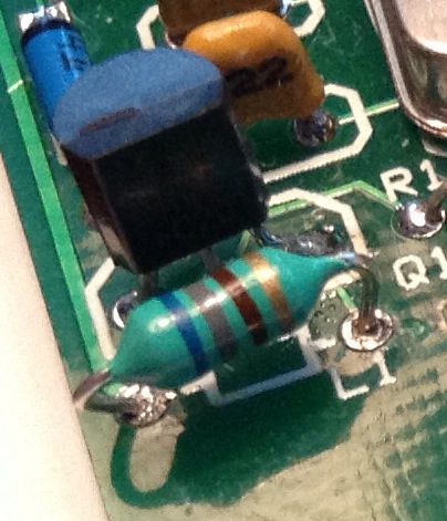
A quick plug into the computer USB port and the PICkit 2 software reported everything was working as expected. No more Vpp Voltage Error. I now had voltage on both sides of the inductor.
So take this as a lesson if you build the PK2 design, make sure the inductor is not bent too tight to break the inner wire. Apparently some of them are very fragile. I will fix the layout in the future so this problem doesn't happen again. I sent the reader an email describing this but have yet to hear if it was their problem as well. I decided to share this with everybody in case anybody else has one of these sitting around with a Vpp Voltage Error.
So take this as a lesson if you build the PK2 design, make sure the inductor is not bent too tight to break the inner wire. Apparently some of them are very fragile. I will fix the layout in the future so this problem doesn't happen again. I sent the reader an email describing this but have yet to hear if it was their problem as well. I decided to share this with everybody in case anybody else has one of these sitting around with a Vpp Voltage Error.
 RSS Feed
